
ASTM A209 TUBO U EN ACERO DE ALEACIÓN PARA CALDERA| ASTM A209 T1 TUBO
VIEW MORE+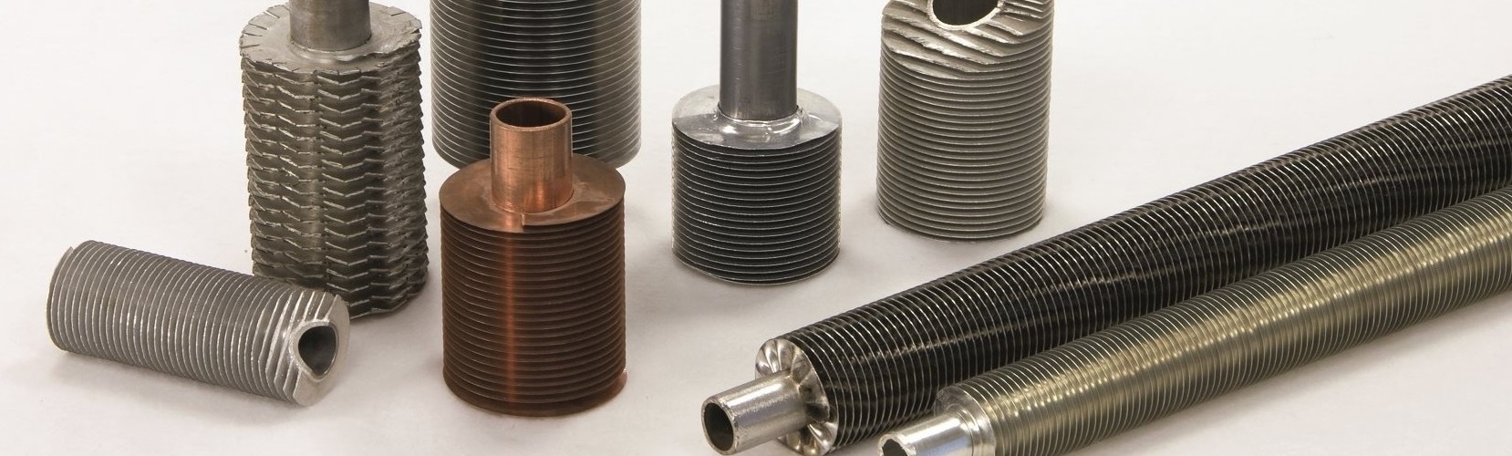
PRODUCTOS
NOTICIAS
- Tubos Aletados por Aporte
- Tubos Riflados para Calderas de Alta Presión
- Qué son la pared de membrana enfriadda por agua?
- Qué es el Corrugado de Hogar para Caldera?
- Tubería Acero al Carbón Flux Lisa
- Qué es Tubería Recta Pernada sin Costura?
- ¿Qué son las curvas a 180º y por qué son clave en la industria?
- Haz de Tubos para Intercambiadores
- Plantilla de Barrenado en Intercambiadores de Calor
- Espejos Tubulares para Intercambiadores
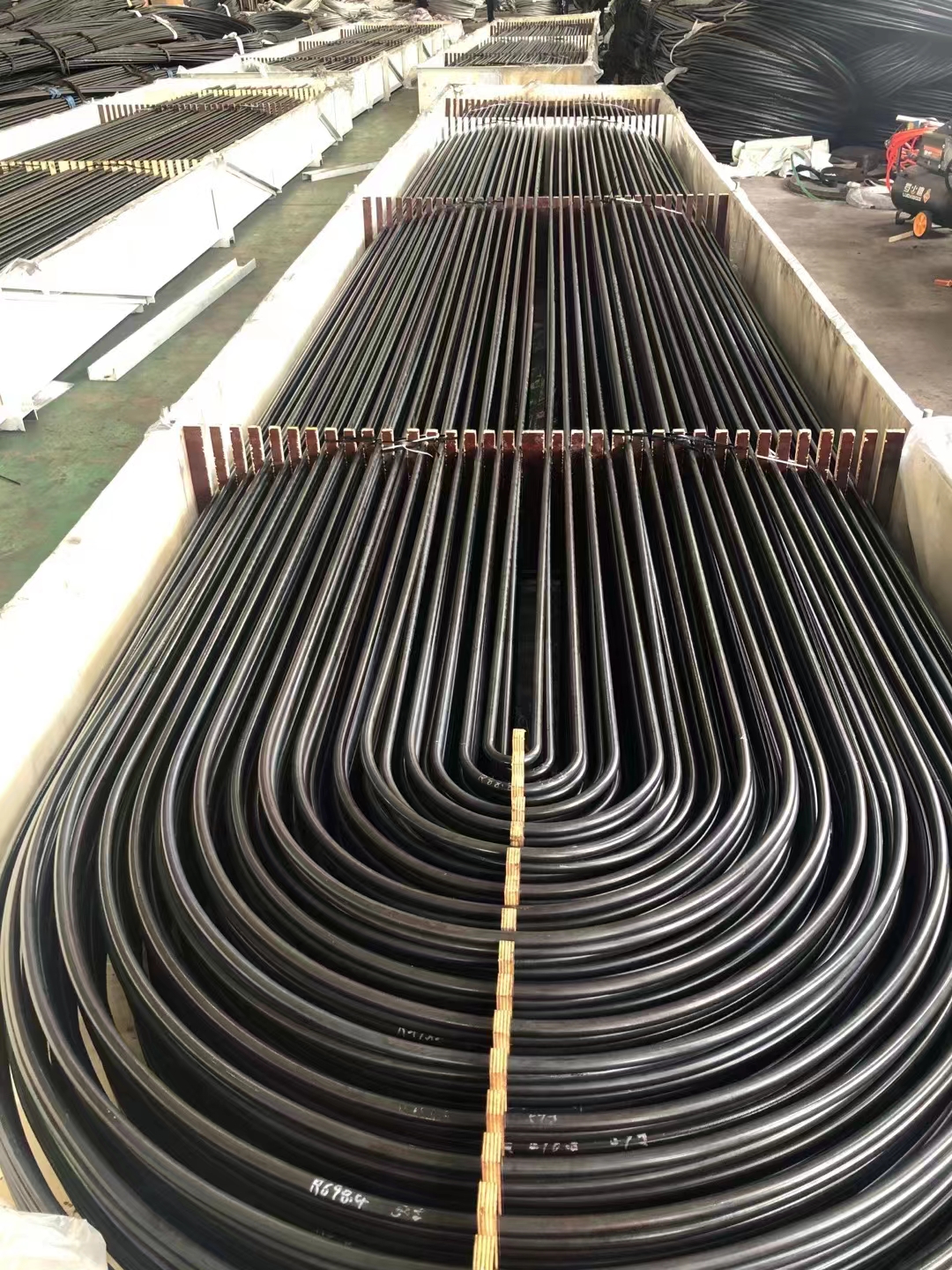
U Bend ASTM A556 Tubos de calentador de agua de alimentación
Especificación estándar ASTM A556/A556M para tubos calentadores de agua de alimentación de acero al carbono estirados en frío sin costura. Cubre tubos de acero al carbono estirados en frío sin costura y con un espesor mínimo de pared, incluido el doblado en forma de tubos en U utilizados en calentadores tubulares de agua de alimentación.
DESCRIPCIóN
Especificación estándar ASTM A556/A556M para tubos calentadores de agua de alimentación de acero al carbono estirados en frío sin costura
1. Alcance de ASTM A556/A556M
1.1 Esta especificación 2 cubre tubos de acero al carbono estirados en frío sin costura y con un espesor mínimo de pared, incluido el doblado en forma de tubos en U, si se especifica, para uso en calentadores tubulares de agua de alimentación.
1.2 Los tamaños de tubería cubiertos serán de 5/8 a 1 1/4 pulgadas. [15,9 a 31,8 mm] de diámetro exterior, inclusive, con espesores de pared mínimos iguales o superiores a 0,045 pulg. [1,1 mm].
1.3 Se proporcionan requisitos complementarios opcionales y, cuando se desee, se indicarán en el pedido.
1.4 Los valores indicados en unidades pulgada-libra o unidades SI deben considerarse por separado como estándar. Dentro del texto, las unidades SI se muestran entre paréntesis. Los valores indicados en cada sistema no son equivalentes exactos; por lo tanto, cada sistema debe usarse independientemente del otro. La combinación de valores de los dos sistemas puede dar como resultado una no conformidad con la especificación. Se aplicarán las unidades pulgada-libra a menos que en el pedido se especifique la designación “M” de esta especificación.
2. Documentos de referencia ASTM A556/A556M
2.1 Normas ASTM:
Especificación A 450/A 450M para requisitos generales para tubos de acero al carbono, de aleación ferrítica y de aleación austenítica
E 30 Métodos de prueba para análisis químicos de acero, hierro fundido, hierro de hogar abierto y hierro forjado
 3. Información para realizar pedidos ASTM A556/A556M
3.1 Los pedidos de material según esta especificación deben incluir lo siguiente según sea necesario para describir adecuadamente el material deseado:
3.1.1 Cantidad (pies, metros o número de piezas),
3.1.2 Nombre del material (tubos de acero sin costura),
3.1.3 Dimensions (outside diameter and minimum wall thickness),
3.1.4 Length (specific or random),
3.1.5 Manufacture (cold drawn),
3.1.6 Grade (chemical composition),
3.1.7 Optional requirements,
3.1.8 Bending Requirements— If order specifies tubes to be bent, the design of the U-tubes shall accompany the order. Purchaser must specify if stress-relief anneal of the U-bends is required,
3.1.9 Test report required (see Certification Section of Specification A 450/A 450M),
3.1.10 Specification number, and
3.1.11 Special requirements and any supplementary requirements selected.
4. ASTM A556/A556M General Requirements
4.1 Material furnished to this specification shall conform to the applicable requirements of the current edition of the Specification A 450/A 450M, unless otherwise provided herein.
5. ASTM A556/A556M Manufacture
5.1 Manufacture—Tubes shall be made by the seamless process and shall be cold drawn.
5.2 Heat Treatment:
5.2.1 Cold-drawn tubes shall be heat treated after the final cold-draw pass at a temperature of1200°F [640°C] or higher to ensure ductility satisfactory for rolling into tube sheets and to meet mechanical properties as specified.
5.2.2 If stress-relief anneal of the U-bends is specified, the anneal shall consist of heating the bent portion within a range of 1100 to 1200°F [585 to 640°C].
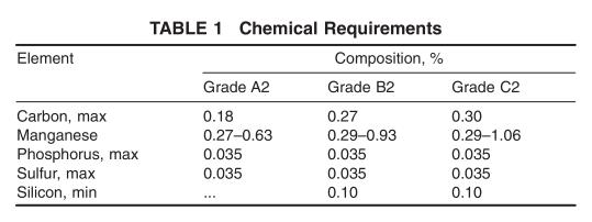
6. ASTM A556/A556M Chemical Composition
6.1 The steel shall conform to one of the requirements as to chemical composition as prescribed in Table 1.
6.2 When a grade is ordered under this specification, supplying an alloy grade that specifically requires the addition of any element other than those listed for the ordered grade in Table 1 is not permitted.
7. ASTM A556/A556M Product Analysis
7.1 When requested in the purchase order, a product analysis shall be made by the manufacturer or supplier from one tube or billet per heat.
7.2 If the original test for product analysis fails, retests of two additional tubes or billets shall be made. Both retests for the elements in question shall meet the requirements of this specification; otherwise, all remaining material in the heat or lot (Note 1) shall be rejected or, at the option of the producer, each tube may be individually tested for acceptance. Tubes that do not meet the requirements of this specification shall be rejected.
N OTE 1—For tension and hardness test requirements, the term lot applies to all tubes prior to cutting, ofthe same nominal diameter and wall thickness which are produced from the same heat ofsteel. When final heat treatment is in a batch-type furnace, a lot shall include only those tubes of the same size and the same heat which are heat treated in the same furnace charge. When the final heat treatment is in a continuous furnace, a lot shall include all tubes ofthe same size and heat, heat treated in the same furnace at the same temperature, time at heat and furnace speed.
7.3 For referee purposes, Test Methods E 30 shall be used.
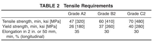
8. ASTM A556/A556M Mechanical Properties
8.1 Tensile Properties—The material shall conform to the requirements as to tensile properties prescribed in Table 2, when pulled in full section.
8.2 Hardness Requirements—The tubes shall not exceed the Rockwell Hardness shown in Table 3.
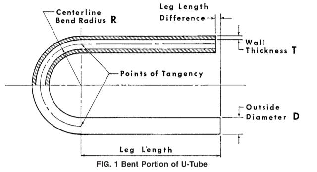
 9. ASTM A556/A556M Permissible Variations in Dimensions (Fig. 1)
9.1 Permissible variations from the specified outside diameter shall not exceed 60.004 in. [0.10 mm] for tubing under
1.0-in. [25.4-mm] outside diameter nor 60.006 in. [0.15 mm] for tubing 1.0 in. [25.4 mm] to 1.25 in. [31.7 mm] inclusive. These tolerances do not apply to the bent portion of the U-tubes. At the bent portion of a U-tube for R = 2 3 D or greater neither the major nor minor diameter of tube shall deviate from nominal by more than 10 %. If 1 1 ⁄ 2 D is specified, tolerances could be greater.
9.2 Permissible variations from the specified minimum wall thickness shall not exceed +20 % or −0. The wall thickness of the tube in U-bent section shall be not less than value
determined by: t f 5 T ~ 2R ! / ~ 2R1D ! (1) where:
t f = wall thickness after bending, in. [mm],
T = specified minimum tube wall thickness, in. [mm],
R = centerline bend radius, in. [mm], and
D = nominal outside tube diameter, in. [mm].
9.3 In the case of U-tubes, the length of the tube legs as measured from the point of tangency of the bend and the tube leg to the end ofthe tube leg shall not be less than specified, but may exceed the specified values by the amount given in Table
4. The difference in lengths of the tube legs shall not be greater than 1/8 in. [3 mm] unless otherwise specified.
9.4 The end of any tube may depart from square by not more than the amount given in Table 5.
9.5 The leg spacing measured between the points of tangency of the bend to the legs shall not vary from the value (2R− specified tube OD) by more than 1/16 in. [1.5 mm] where R is the centerline bend radius.
9.6 The bent portion of the U-tube shall be substantially uniform in curvature and not exceed 6 1/16 in. [61.5 mm] ofthe normal centerline radius.
10. ASTM A556/A556M Workmanship, Finish, and Appearance
10.1 Finished tubes shall be free from scale but may have a superficial oxide film on the surfaces. Alight oxide scale on the outside and inside surfaces of U-bend shall be allowed for tubes which have been heat treated.
10.2 Finished tubes shall be reasonably straight and have smooth ends free from burrs. Tubes shall have a workmanlike finish and shall be free of surface imperfections that cannot be removed within the allowable wall tolerances. Removal of surface imperfections such as handling marks, straightening marks, light mandrel and die marks, shallow pits, and scale pattern will not be required provided they are within the allowable wall tolerances.
10.3 Finished tubes shall be coated both on the outside and the inside diameter to prevent corrosion in transit. The type of coating applied should be mutually agreed upon and specified in the order.
11. ASTM A556/A556M Mechanical Tests Required
11.1 Tension Test—One tension test shall be made on a specimen for lots of not more than 50 tubes. Tension tests shall be made on specimens from two tubes for lots of more than 50 tubes (Note 1).
11.2 Flattening Test—One flattening test shall be made on specimens taken from each end of one finished tube, not the one used for the flaring test, from each lot ofnot more than 125 tubes or fraction thereof.
11.3 Flaring Test—One flaring test shall be made on specimens taken from each end of one finished tube, not the one used for flattening test, from each lot of not more than 125 tubes or fraction thereof.
11.4 Hardness Test—Brinell or Rockwell hardness tests shall be made on specimens from two tubes from each lot (Note 1).
11.5 Hydrostatic Test—Each U-tube shall be subjected to a hydrostatic test, using a noncorrosive fluid, or when agreed upon between the purchaser and manufacturer, they may be tested at 1 1 ⁄ 2 times the specified design working pressure.
12. ASTM A556/A556M Nondestructive Test (Electric Test)
12.1 Each tube shall be tested after the finish heat treatment following the final cold-drawn pass by passing through a nondestructive tester capable of detecting defects on the entire cross section of the tube, in accordance with Specification A 450/A 450M.
13. ASTM A556/A556M Packaging and Package Marking
13.1 The tubing shall be packaged or bundled in such a manner as to prevent damage in ordinary handling and transportation and identified by a tag with the name of the manufacturer, purchase order number, specification number and grade, and size.
13.2 In the case of U-tubes, each box shall be palletized and legibly marked showing the manufacturer’s name, purchase order number, specification number and grade, size, and identification of items contained.
13.3 Codificación de barras: además de los requisitos de 13.1 y 13.2, la codificación de barras es aceptable como método de identificación complementario. El comprador podrá especificar en el pedido un sistema de codificación de barras específico a utilizar.
14. Palabras clave ASTM A556/A556M
Tubos calentadores de agua de alimentación ASTM A556|Tubos calentadores de agua de alimentación de acero al carbono|Tubos calentadores de agua de alimentación ASTM A556 con curva en U
Products
-
-
Tubo de intercambiador de calor de U-Bend
VIEW MORE+ -
U Bend Astm A214 Tubos | U Tubos de condensador de Bend
VIEW MORE+


Copyright © 2015-2023 T.S. Industrial Corporation Limited 
请输入搜索关键字
确定