
ASTM A209 TUBO U EN ACERO DE ALEACIÓN PARA CALDERA| ASTM A209 T1 TUBO
VIEW MORE+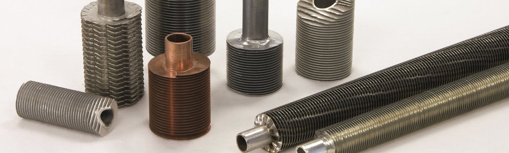
PRODUCTOS
NOTICIAS
- Qué son Anillas Separadoras para Tubos Aletados?
- Tubos Aletados por Aporte
- Tubos Riflados para Calderas de Alta Presión
- Qué son la pared de membrana enfriadda por agua?
- Qué es el Corrugado de Hogar para Caldera?
- Tubería Acero al Carbón Flux Lisa
- Qué es Tubería Recta Pernada sin Costura?
- ¿Qué son las curvas a 180º y por qué son clave en la industria?
- Haz de Tubos para Intercambiadores
- Plantilla de Barrenado en Intercambiadores de Calor
Tu tubo Astm A688 u tubos de calentador de agua de alimentación
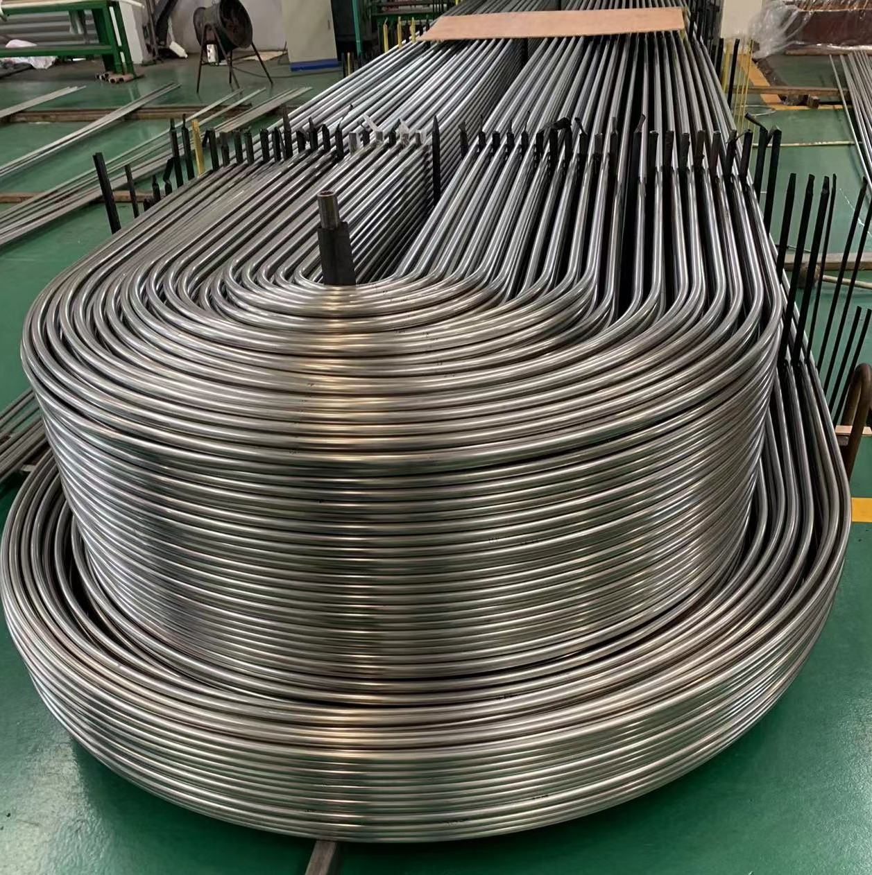
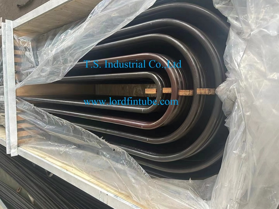
ASTM A688/A688M cubre los tubos soldados de acero inoxidable austenítico para calentadores de agua de alimentación, incluidos los doblados, si se especifica, en forma de tubos en U para su aplicación en calentadores tubulares de agua de alimentación. El doblado en U se suministrará en estado recocido en solución.
DESCRIPCIóN
Tubos de calentador de agua de alimentación de acero inoxidable austenítico soldados con autógena estándar ASTM A688/A688M
1. Alcance de ASTM A688/A688M
1.1 Esta especificación 2 cubre los tubos soldados de acero inoxidable austenítico para calentadores de agua de alimentación, incluidos aquellos doblados, si se especifican, en forma de tubos en U para su aplicación en calentadores tubulares de agua de alimentación.
1.2 Los tamaños de tubería cubiertos deben ser de 5 ⁄ 8 a 1 pulg. [15,9 a 25,4 mm], incluido el diámetro exterior, y espesores de pared promedio o mínimos de 0,028 pulg. [0,7 mm] y más.
1.3 Los valores indicados en unidades pulgada-libra o unidades SI deben considerarse por separado como estándar. Dentro del texto, las unidades SI se muestran entre paréntesis. Los valores indicados en cada sistema no son equivalentes exactos; por lo tanto, cada sistema se utilizará independientemente del otro. La combinación de valores de los dos sistemas puede dar como resultado una no conformidad con la especificación .
2. Documentos de referencia ASTM A688/A688M
2.1 Normas ASTM:
A 262 Prácticas para detectar la susceptibilidad al ataque intergranular en aceros inoxidables austeníticos A 480/A 480M Especificación para requisitos generales para placas, láminas y tiras de acero inoxidable laminado plano y resistentes al calor
A 941 Terminología relacionada con el acero, el acero inoxidable, las aleaciones relacionadas y las ferroaleaciones
A 1016/A 1016M Especificación para requisitos generales para tubos de acero aleado ferrítico, acero aleado austenítico y acero inoxidable
E 527 Práctica para la numeración de metales y aleaciones (UNS)
2.2 Otra norma:
Práctica SAE J1086 para numeración de metales y aleaciones (UNS)
3. Terminología ASTM A688/A688M
3.1 Definiciones de términos: para conocer las definiciones de los términos utilizados en esta especificación, consulte Terminología A 941.
4. Información para realizar pedidos ASTM A688/A688M
4.1 It is the responsibility of the purchaser to specify all requirements that are necessary for material under this specification. Such requirements may include, but are not limited to, the following:
4.1.1 Quantity (length or number of pieces),
4.1.2 Material description,
4.1.3 Dimensions—Outside diameter, wall thickness (minimum or average wall), and length,
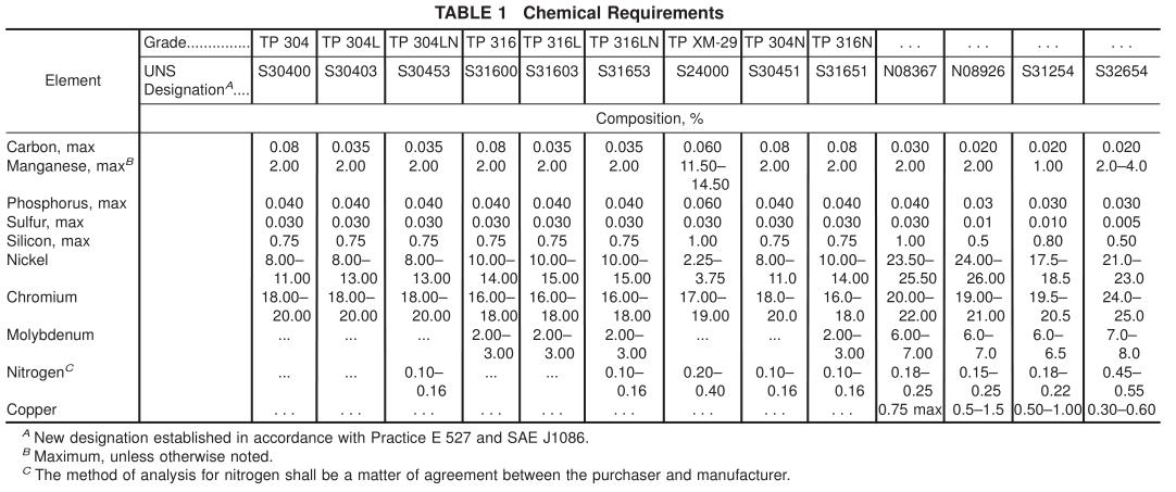
4.1.4 Grade (chemical composition) (Table 1),
4.1.5 U-bend requirements, if order specifies bending, U-bend schedules or drawings shall accompany the order,
4.1.6 Optional requirements—Purchaser shall specify if annealing of the U-bends is required or whether tubes are to behydrotested or air tested (see 11.6)
4.1.7 Supplementary requirements—Purchaser shall specify on the purchase order if material is to be eddy current tested in accordance with Supplementary Requirements S1 or S2, and ifspecial test reports are required under Supplementary Requirement S3, and,
4.1.8 Any special requirements.
5. ASTM A688/A688M General Requirements
5.1 Material furnished to this specification shall conform to the applicable requirements of the latest published edition of Specification A 1016/A 1016M unless otherwise provided herein.
6. ASTM A688/A688M Materials and Manufacture
6.1 The tube shall be made from flat-rolled steel by an automatic welding process with no addition of filler metal.
6.2 Subsequent to welding and prior to final heat treatment, the tubes shall be cold worked either in both the weld and base metal, or in the weld metal only. The method ofcold work may be specified by the purchaser. When cold drawn, the purchaser may specify the minimum amount of reduction in cross sectional area or wall thickness, or both.
6.3 Many surface contaminants may have detrimental effects on high temperature properties or corrosion resistance of tubing. Contamination by copper, lead, mercury, zinc, chlorides, or sulfur may be detrimental to stainless steels. The manufacturer shall employ techniques that minimize surface contamination by these elements.
7. ASTM A688/A688M Cleaning Before Annealing
7.1 All lubricants of coatings used in the manufacture of straight-length tube or in the bending shall be removed from all surfaces prior to any annealing treatments. U-bends on which a lubricant had been applied to the inside surface during bending shall have the cleanness of their inside surface confirmed by blowing close fitting acetone-soaked felt plugs through 10 % ofthe tubes ofeach bend radius. Dry, oil-free, air or inert gas shall be used to blow the plugs through the tubes. If the plugs blown through any tube shows more than a light gray discoloration, all tubes that have had a lubricant applied to the inside surface during bending shall be recleaned. After recleaning 10 % of the tubes of each bend radius whose inside surface had been subjected to bending lubricants shall be retested.
8. ASTM A688/A688M Heat Treatment
8.1 All finished straight tubing or straight tubing ready for U-bending shall be furnished in the solution-annealed condition. The annealing procedure, except for N08367 and N08926,
shall consist of heating the material to a minimum temperature of 1900°F [1040°C] followed by a rapid cooling to below 700°F [370°C]. The cooling rate shall be sufficiently rapid to
prevent harmful carbide precipitation as determined in Section
13. UNS N08367 shall be solution annealed from 2025°F [1107°C] minimum followed by rapid quenching.
8.2 N08926 shall be heat-treated to a minimum temperature of 2010°F [1100°C] followed by quenching in water or rapidly cooling by other means.
8.3 If heat treatment of U-bends is specified, it shall satisfy the annealing procedure described in 8.1 and 8.2, and shall be done as follows:
8.3.1 The heat treatment shall be applied to the U-bend area plus approximately 6 in. [150 mm] of each leg beyond the tangent point of the U-bend.
8.3.2 If the heat treatment specified in 8.3 is accomplished by resistance-heating methods wherein electrodes are clamped to the tubes, the clamped areas shall be visually examined for arc burns. Burn indications shall be cause for rejection unless they can be removed by local polishing without encroaching upon minimum wall thickness.
8.3.3 Temperature control shall be accomplished through the use of optical or emission pyrometers, or both. No temperature-indicating crayons, lacquers, or pellets shall be used.
8.3.4 The inside ofthe tube shall be purged with a protective or an inert gas atmosphere during heating and cooling to below 700°F [370°C] to prevent scaling of the inside surface. The atmosphere should be noncarburizing.
9. ASTM A688/A688M Surface Condition
9.1 The straight tubes, after final annealing, shall be pickled using a solution of nitric and hydrofluoric acids followed by flushing and rinsing in water. If bright annealing is performed,
this requirement does not apply.
9.2 Alight oxide scale on the outside surface ofU-bend area shall be permitted for tubes which have been electric-resistance heat treated after bending.
10. ASTM A688/A688M Chemical Composition
10.1 Product Analysis:
10.1.1 When requested in the purchase order, a product analysis shall be made by the supplier from one tube or coil of steel per heat. The chemical composition shall conform to the requirements shown in Table 1.
10.1.2 A product analysis tolerance of Specification A 480/ A 480M shall apply. The product analysis tolerance is not applicable to the carbon content for material with a specified maximum carbon of 0.04 % or less.
10.1.3 Ifthe original test for product analysis fails, retests of two additional lengths of flat-rolled stock or tubes shall be
11. ASTM A688/A688M Mechanical Requirements
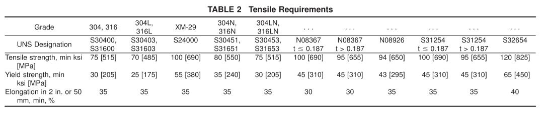
11.1 Tensile Properties:
11.1.1 The material shall conform to the tensile properties shown in Table 2.
11.1.2 One tension test shall be made on a specimen for lots of not more than 50 tubes. Tension tests shall be made on specimens from two tubes for lots of more than 50 tubes (Note 2).
11.2 Hardness:
11.2.1 Grade TP XM-29 tubes shall have a hardness number not exceeding 100 HRB or its equivalent. Tubes of all other grades shall have a hardness number not exceeding 90 HRB or its equivalent. This hardness requirement is not to apply to the bend area of U-bend tubes which are not heat treated after bending.
11.2.2 Brinell or Rockwell hardness tests shall be made on specimens from two tubes from each lot.
N OTE 2—For tension, hardness, and corrosion test requirements, the term “lot” applies to all tubes prior to cutting to length, of the same nominal diameter and wall thickness, produced from the same heat of steel and annealed in a continuous furnace at the same temperature, time at heat, and furnace speed.
11.3 Reverse Bend Test:
11.3.1 One reverse bend test shall be made on a specimen from each 1500 ft [460 m] of finished tubing.
11.3.2 A section 4 in. [100 mm] minimum in length shall be split longitudinally 90° on each side of the weld. The sample shall then be opened and bent around a mandrel with a maximum thickness of four times the wall thickness, with the mandrel parallel to the weld and against the original outside surface of the tube. The weld shall be at the point of maximum
bend. There shall be no evidence of cracks, or of overlaps resulting from the reduction in thickness of the weld area by cold working. When the geometry or size of the tubing make it difficult to test the sample as a single piece, the sample may be
11.4 Flattening Test—Flattening tests shall be made on specimens from each end ofone finished tube, not the one used for the flange test, from each lot (Note 1).
11.5 Flange Test—Flange tests shall be made on specimens from each end of one finished tube, not the one used for the flattening test, from each lot (Note 1).
11.6 Pressure Test:
11.6.1 Each straight tube or each U-tube after completion of the bending and post-bending heat treatment, shall be pressure tested in accordance with one of the following paragraphs as specified by the purchaser.
11.6.1.1 Hydrostatic Test—Each tube shall be given an internal hydrostatic test in accordance with Specification
A 1016/A 1016M, except that the test pressure and hold time, when other than that stated in Specification A 1016/A 1016M, shall be agreed upon between purchaser and manufacturer.
11.6.1.2 Air Underwater Test—Each tube shall be air underwater tested in accordance with Specification A 1016/A 1016M.
12. ASTM A688/A688M Nondestructive Test (Electric Test)
12.1 Each straight tube shall be tested after the finish heat treatment by passing it through a nondestructive tester capable of detecting defects on the entire cross section of the tube, in accordance with Specification A 1016/A 1016M.
13. ASTM A688/A688M Corrosion Resisting Properties
13.1 One full section sample 1 in. [25.4 mm] long from the center of a sample tube of the smallest radius bend which is heat treated shall be tested in the heat treated condition in accordance with Practices A 262.
13.2 One full-section sample 1 in. [25.4 mm] long from each lot (Note 2) ofstraight tubes shall be tested in the finished condition in accordance with Practices A 262.
13.3 The appearance of any fissures or cracks in the test specimen when evaluated in accordance with Practices A 262 indicating the presence of intergranular attack, shall be cause for rejection of that lot.
14. ASTM A688/A688M Permissible Variations in Dimensions (Fig. 1)
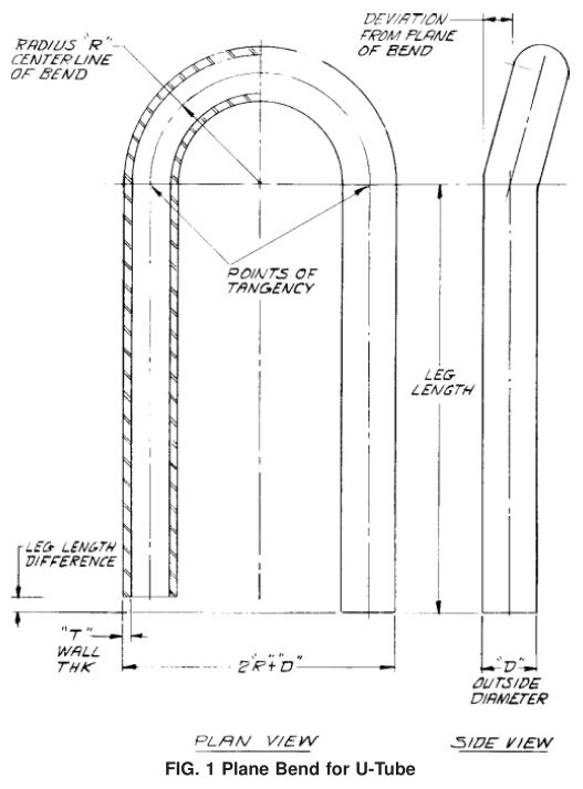
14.1 Permissible variations from the specified outside diameter shall be in accordance with Specification A 1016/A 1016M. Those tolerances do not apply to the bent portion of the U-tubes. At the bent portion of a U-tube for R = 2 3 D or greater, neither the major nor minor diameter of the tube shall deviate from the nominal diameter prior to bending by more than 10 %. If less than 2 3 D is specified, tolerances could be greater.
14.2 Permissible Variations from the Specified Wall Thickness:
14.2.1 Permissible variations from the specified minimum wall thickness shall not exceed +20%− 0.
14.2.2 Permissible variations from the specified average wall thickness are 610 % of the nominal wall thickness.
14.2.3 The wall thickness of the tube in the U-bent section shall not be less than value determined by the equation:
t f 5
4RT
4 R 1 D
where:
t f = wall thickness after bending, in. [mm],
T = minimum wall thickness of 14.2.1 or 14.2.2, in. [mm],
R = centerline bend radius, in. [mm], and
D = nominal outside tube diameter, in. [mm].
14.3 Permissible Variations from the Specified Length:
14.3.1 Straight Lengths—The maximum permissible variations for lengths 24 ft [7.3 m] and shorter shall be + 1 ⁄ 8 in. [3mm], −0; for lengths longer than 24 ft [7.3 mm], an additional
over tolerance of + 1 ⁄ 8 in. [3 mm] for each 10 ft [3 m], or fraction thereof, shall be permitted up to a maximum of+ 1 ⁄ 2 in. [13 mm].
14.3.2 U-Bends—In the case of U-tubes, the length of the tube legs as measured from the point of tangency of the bend and the tube leg to the end ofthe tube leg, shall not be less than specified, but may exceed the specified values by the amount given in Table 3. The difference in lengths ofthe tube legs shall not be greater than 1/8in. unless otherwise specified. 14.4 The end of any tube may depart from square by not more than the amount given in Table 4.
14.5 The leg spacing measured between the points of tangency of the bend to the legs shall not vary from the value (2 R − specified tube outside diameter) by more than 1/16 in.[1.5 mm] where R is the center-line bend radius.
14.6 La porción doblada del tubo en U deberá tener una curvatura sustancialmente uniforme y no deberá exceder 6 1 ⁄ 16 pulgadas [1,5 mm] del radio nominal de la línea central.
14.7 La desviación permitida del plano de curvatura (Fig. 1) no deberá exceder 1/16 de pulgada. [1,5 mm] medido desde los puntos de tangencia.
15. Mano de obra, acabado y apariencia ASTM A688/A688M
15.1 Los tubos adquiridos según esta especificación están destinados a su uso en intercambiadores de calor y se insertarán a través de orificios ajustados en deflectores o placas de soporte, o ambos, espaciados a lo largo de la longitud del tubo. Los extremos de los tubos también se insertarán en orificios muy ajustados en una placa de tubos y se expandirán y podrán soldarse en ellos. Los tubos deberán poder soportar la expansión y
doblarse sin mostrar grietas ni fallas, y deberá tener un acabado razonablemente recto y adecuado para el propósito previsto.
15.2 La contaminación residual de sal de cloruro de la superficie interior y exterior de la tubería en el momento del embalaje para su envío desde la planta no deberá exceder una concentración de 1 mg/pie 2 [10,7 mg/m 2 ] de la superficie del tubo. Un tubo de cada quinientas piezas se comprobará inmediatamente antes del embalaje para su envío para detectar contaminación por sal de cloruro mediante un procedimiento acordado entre el fabricante y el comprador.
16. Inspección ASTM A688/A688M
16.1 El inspector que representa al comprador tendrá acceso, en todo momento, a aquellas áreas donde se realizan inspecciones y pruebas en el material solicitado por el comprador. El fabricante deberá brindar al inspector todas las facilidades razonables para convencerlo de que el material se suministra de acuerdo con esta especificación. Todas las pruebas e inspecciones requeridas se realizarán en el lugar de fabricación antes del envío, a menos que se especifique lo contrario, y se llevarán a cabo de manera que no interfieran innecesariamente con la operación de las obras.
Tubo en U con curvatura ASTM A688|Tubos para calentadores de agua de alimentación|Tubos con curvatura en U para calentadores de agua de alimentación
Products
-
-
Tubo de intercambiador de calor de U-Bend
VIEW MORE+ -
U Bend Astm A214 Tubos | U Tubos de condensador de Bend
VIEW MORE+


Copyright © 2015-2023 T.S. Industrial Corporation Limited 
请输入搜索关键字
确定